Understanding electrical systems can be daunting, especially when it comes to wiring diagrams. A clear and concise diagram can make all the difference in successfully setting up your 12-volt systems. This guide will simplify the process for you.
Whether you’re working on a boat, RV, or any other 12-volt project, having the right information is crucial. A well-structured wiring diagram helps prevent mistakes and ensures everything functions smoothly. Let’s dive into the essentials.

12 Volt Amp Meter Wiring Diagram
12 Volt Amp Meter Wiring Diagram
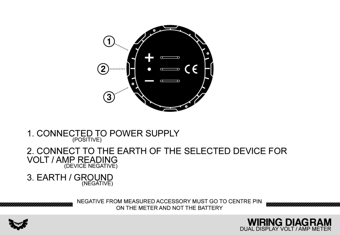
The 12 Volt Amp Meter Wiring Diagram is essential for monitoring your system’s current. It provides a visual representation of how to connect your amp meter to the power source and load. This clarity helps avoid confusion during installation.
When wiring your amp meter, start by identifying the positive and negative terminals. Connect the positive terminal to the power source and the negative terminal to the load. This setup allows accurate current readings while ensuring safety.
It’s also important to use appropriate wire gauges for your connections. Thicker wires can handle higher currents without overheating, which is vital for maintaining system integrity. Always refer to your amp meter’s specifications for guidance on wire sizes.
Lastly, double-check all connections before powering up your system. A quick inspection can save you from potential issues down the line. Proper installation not only enhances performance but also extends the lifespan of your equipment.
With a solid understanding of the 12 Volt Amp Meter Wiring Diagram, you’re well on your way to successfully managing your electrical systems. Take your time, follow the guidelines, and enjoy your projects with confidence.