Understanding the wiring of a 240-volt well pump is essential for anyone looking to install or troubleshoot their system. Proper wiring ensures efficiency and safety, making it crucial to follow the right guidelines.
Many homeowners find themselves confused by the complexities of electrical systems. A clear wiring diagram can simplify the process, helping you visualize how everything connects and operates.

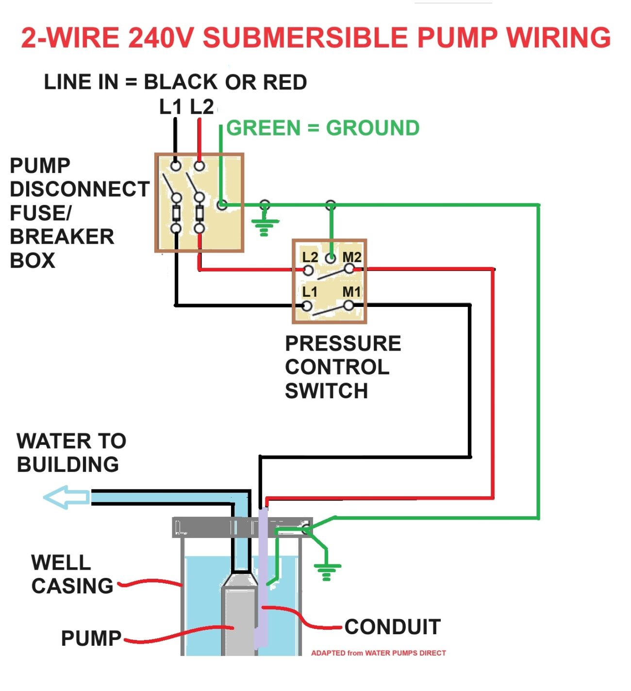
240 Volt Well Pump Wiring Diagram
240 Volt Well Pump Wiring Diagram
A 240-volt well pump typically requires a dedicated circuit to function correctly. This circuit should be equipped with a double-pole breaker to handle the higher voltage safely. Always ensure that your wiring matches local codes.
When creating a wiring diagram, start by identifying the components: the pump, pressure switch, and control box. Each part plays a vital role in the overall operation of your well system.
Labeling each wire in your diagram can prevent confusion during installation. Use color-coded wires for easy identification, ensuring that connections are made correctly to avoid potential hazards.
Lastly, always prioritize safety when working with electricity. If you’re unsure about any step in the process, consulting a professional electrician can save you time and prevent costly mistakes.
With a clear understanding of your 240-volt well pump wiring diagram, you can confidently tackle your installation or repair project. Remember to follow safety protocols and consult experts when needed for peace of mind.