Understanding your vehicle’s wiring can seem daunting, but it doesn’t have to be. A clear grasp of the 3 wire camshaft sensor wiring diagram can simplify troubleshooting and repairs, making your automotive experience smoother.
Many car owners face issues with their camshaft sensors, leading to performance problems. Knowing how to read and interpret the wiring diagram is essential for effective diagnostics and repairs.

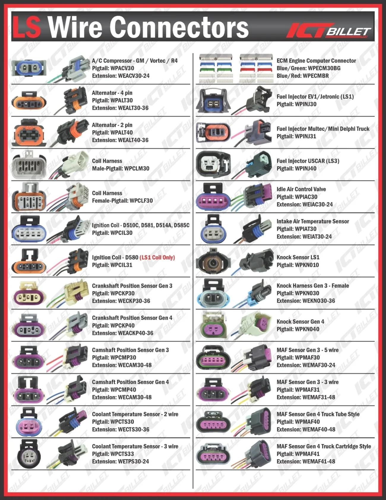
3 Wire Camshaft Sensor Wiring Diagram
3 Wire Camshaft Sensor Wiring Diagram
The 3 wire camshaft sensor typically includes a power supply, ground, and signal wire. Each wire plays a crucial role in ensuring the sensor functions correctly and communicates with the engine control unit.
When examining the wiring diagram, identify the color codes for each wire. This will help you connect or replace wires accurately, preventing potential damage to your vehicle’s electrical system.
Additionally, understanding the sensor’s location is vital. Usually found near the engine, accessing it may require removing other components. Familiarize yourself with your vehicle’s layout for easier access during repairs.
Regular maintenance of your camshaft sensor can prevent future issues. Keeping an eye on wiring integrity and connections will ensure optimal performance and longevity of your vehicle’s engine system.
In conclusion, mastering the 3 wire camshaft sensor wiring diagram empowers you to tackle automotive challenges confidently. With a little knowledge and practice, you can enhance your vehicle’s performance and reliability.