Understanding the intricacies of your motorcycle’s electrical system can seem daunting. However, with the right guidance, you can easily navigate through the wiring processes and enhance your bike’s performance.
One essential component to grasp is the 4 Pin CDI (Capacitor Discharge Ignition) system. This system plays a crucial role in managing your engine’s ignition timing and overall efficiency.

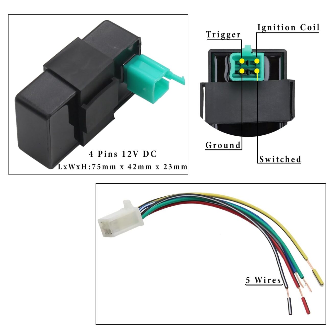
4 Pin Cdi Wiring Diagram
4 Pin Cdi Wiring Diagram
The 4 Pin CDI wiring diagram is vital for anyone looking to troubleshoot or upgrade their ignition system. It typically includes connections for power, ground, trigger, and output to the ignition coil.
When examining the wiring diagram, pay close attention to color codes and pin assignments. Each wire has a specific function, and understanding these can prevent costly mistakes during installation or repairs.
For those new to motorcycle maintenance, following the wiring diagram step-by-step can simplify the process. Make sure to double-check each connection before powering up your bike to avoid any electrical issues.
In conclusion, mastering the 4 Pin CDI wiring diagram not only boosts your confidence but also enhances your motorcycle’s performance. With practice and patience, you’ll become adept at handling these electrical systems like a pro.