Understanding electrical components can be daunting, especially when it comes to wiring diagrams. A 4 pin relay is a common device used in various applications, making it essential to grasp its wiring basics. This knowledge can save time and prevent errors.
Whether you’re working on automotive projects or home automation, knowing how to read a 4 pin relay wiring diagram is crucial. This guide will simplify the process, ensuring you feel confident tackling your next project.

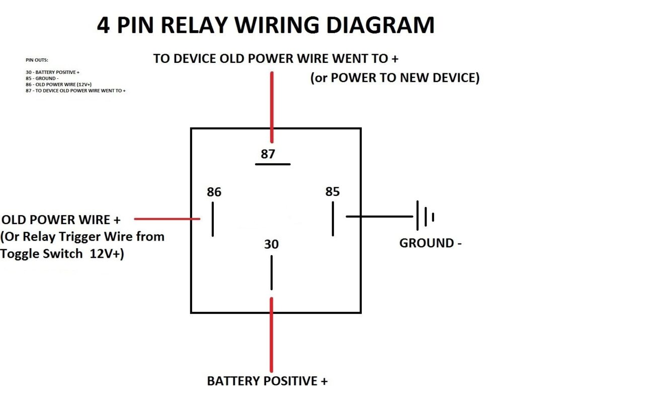
4 Pin Relay Wiring Diagram
4 Pin Relay Wiring Diagram
A 4 pin relay typically consists of four terminals: two for the coil and two for the switch. The coil terminals activate the relay, while the switch terminals control the connected device. Understanding this layout is key to effective wiring.
When wiring a 4 pin relay, connect one coil terminal to the power source and the other to ground. This setup allows the relay to activate when power flows through the coil. Make sure to use appropriate gauge wires for safety.
The switch terminals can be connected to your device, such as a light or motor. When the relay activates, it closes the circuit, allowing current to flow and powering your device. This simple mechanism is widely used in various applications.
Always double-check your connections before powering up the circuit. Incorrect wiring can lead to malfunctions or damage to your components. Taking a moment to verify everything ensures a smooth operation and longevity of your devices.
Mastering the 4 pin relay wiring diagram opens up numerous possibilities for projects. With practice, you’ll find it easier to implement relays in various applications, enhancing your skills and confidence in electrical work.