Understanding electrical systems can be daunting, but with the right resources, it becomes manageable. One essential component in many circuits is the relay, specifically the 4 wire relay, which serves various applications.
Wiring a 4 wire relay correctly is crucial for ensuring your devices function properly. This guide will help you grasp the basics of a 4 wire relay wiring diagram and how to implement it effectively.

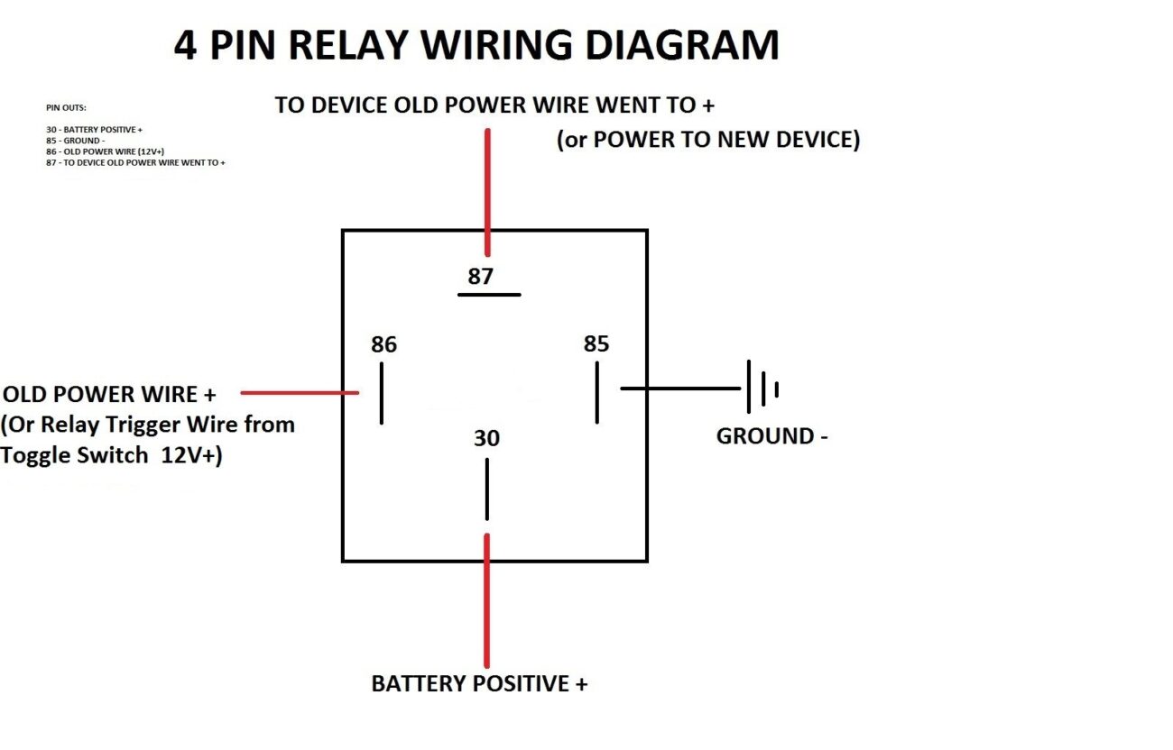
4 Wire Relay Wiring Diagram
4 Wire Relay Wiring Diagram
A 4 wire relay typically consists of two input wires and two output wires. The input wires connect to the control circuit, while the output wires connect to the load. Understanding this setup is key to successful wiring.
When wiring a 4 wire relay, start by identifying the terminals. Usually, you’ll find terminals labeled as A1 and A2 for the coil, and terminals 11 and 12 for the load. Following this layout simplifies the process significantly.
Ensure you use appropriate gauge wires to handle the current load. Using wires that are too thin can lead to overheating and potential failure of your relay. Always prioritize safety when working with electrical components.
Testing your connections before finalizing everything is a good practice. This step helps identify any issues early on, ensuring your relay operates smoothly without any hiccups.
With a clear understanding of the 4 wire relay wiring diagram, you can confidently tackle your projects. Proper wiring not only enhances performance but also extends the lifespan of your devices. Happy wiring!