Understanding the wiring of your motorcycle’s CDI can seem daunting, but it doesn’t have to be. A clear diagram can simplify the process and help you troubleshoot issues effectively. Knowing how to read these diagrams is essential for any bike enthusiast.
One common type of wiring diagram is the 6 Pin DC CDI Wiring Diagram. This diagram is crucial for ensuring that your ignition system functions properly. With the right information, you can enhance your bike’s performance and reliability.

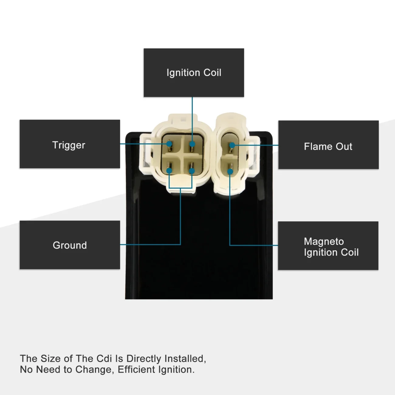
6 Pin Dc Cdi Wiring Diagram
6 Pin Dc Cdi Wiring Diagram
The 6 Pin DC CDI Wiring Diagram typically includes six essential connections. These connections are vital for the proper functioning of your motorcycle’s ignition system. Understanding each pin’s role will help you diagnose problems quickly.
Each pin in the diagram corresponds to specific components like the ignition coil, battery, and ground. By following the wiring layout, you can ensure that everything is connected correctly. This prevents potential electrical issues that could arise from incorrect wiring.
When working with a 6 Pin DC CDI Wiring Diagram, always double-check your connections. A small mistake can lead to significant problems down the line. Take your time to ensure everything is in place before testing your bike.
In conclusion, mastering the 6 Pin DC CDI Wiring Diagram is a valuable skill for any motorcycle owner. With a bit of patience and practice, you’ll be able to tackle wiring issues confidently and keep your bike running smoothly.