Understanding air conditioner systems can be daunting, especially when it comes to wiring. A clear grasp of the components involved is essential for effective maintenance and troubleshooting. One key element is the air conditioner contactor.
The contactor acts as a switch, controlling the power supply to the compressor and fan. Knowing how to read an air conditioner contactor wiring diagram can simplify repairs and enhance your DIY skills. Let’s dive into this topic!

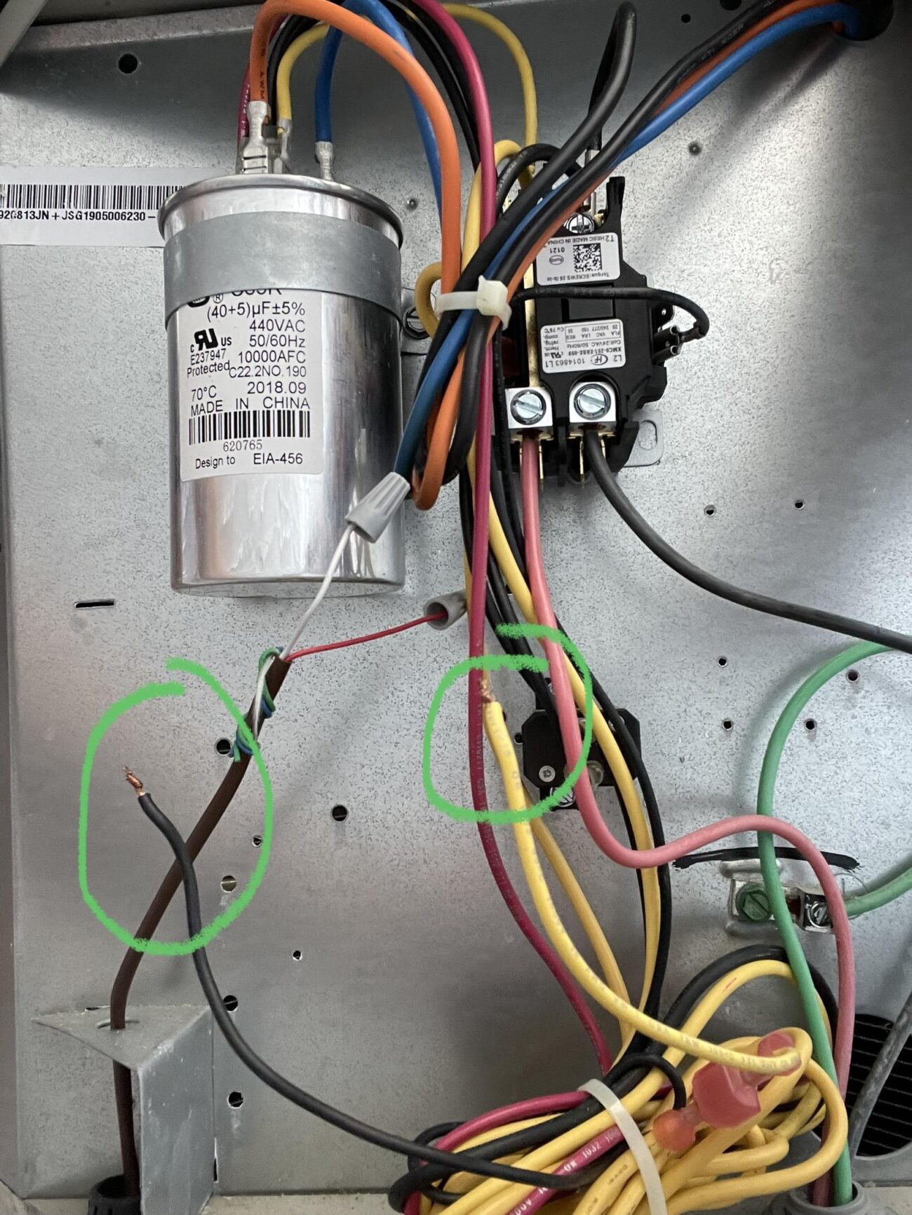
Air Conditioner Contactor Wiring Diagram
Air Conditioner Contactor Wiring Diagram
The air conditioner contactor wiring diagram illustrates how various components connect within the system. Typically, it includes the contactor, capacitor, and thermostat connections. Familiarizing yourself with this diagram can save time during repairs.
When examining the wiring diagram, pay attention to color codes and terminal labels. These details help ensure you connect wires correctly, preventing potential damage to your unit. Always double-check your connections before powering on the system.
Additionally, understanding the function of each wire is crucial. For instance, the common wire usually connects to the thermostat, while the load wires connect to the compressor and fan. This knowledge helps in diagnosing issues effectively.
In conclusion, mastering the air conditioner contactor wiring diagram empowers you to tackle repairs confidently. With practice and attention to detail, you can maintain your air conditioning system efficiently and ensure its longevity.