Understanding the wiring of a brushless hub motor can seem daunting, but it’s quite manageable with the right guidance. This knowledge is essential for anyone looking to build or repair electric bikes or similar vehicles.
A clear wiring diagram simplifies the process, making it easier to connect components correctly. Knowing how to interpret these diagrams can save time and prevent potential issues during installation.

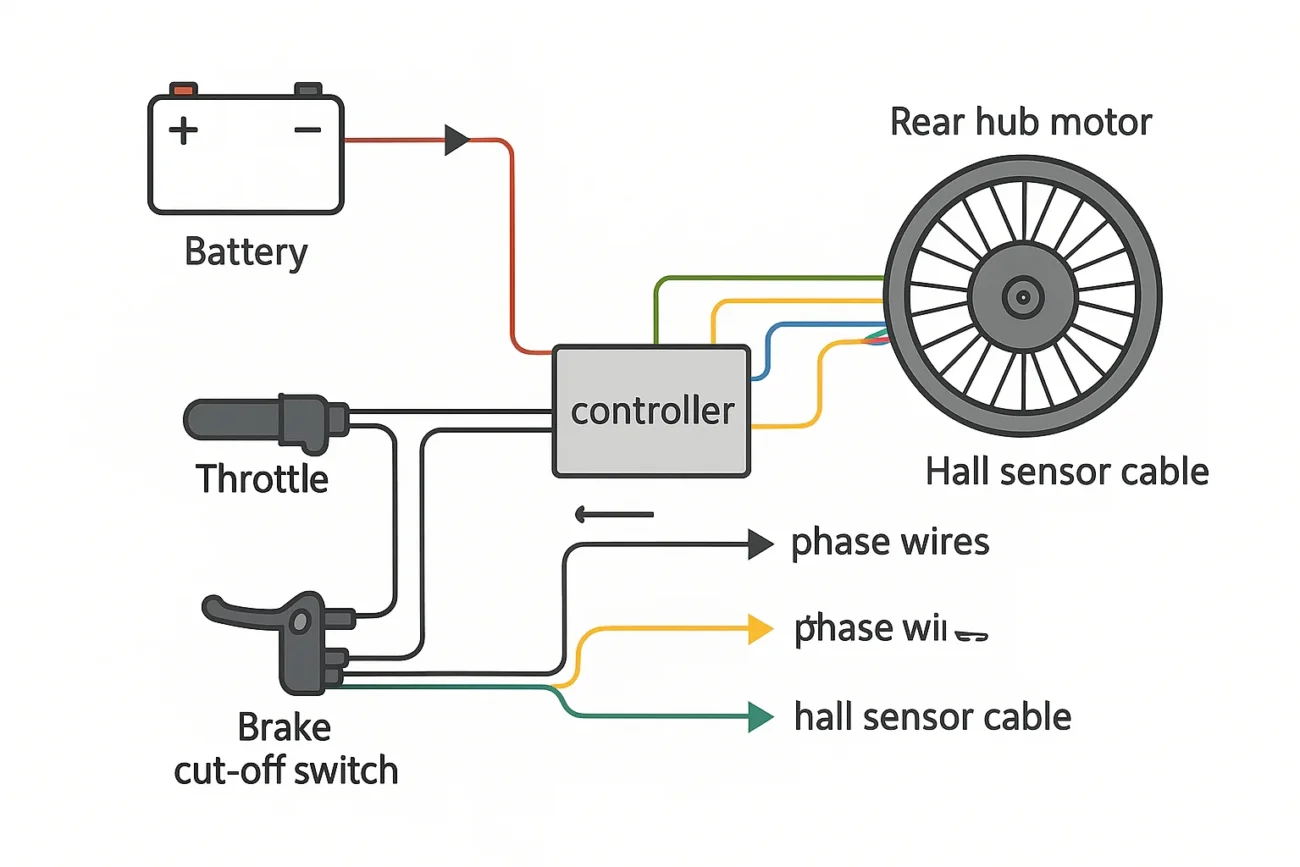
Brushless Hub Motor Wiring Diagram
Brushless Hub Motor Wiring Diagram
The brushless hub motor wiring diagram typically includes three main wires: phase wires, hall sensor wires, and power supply wires. Each wire plays a crucial role in ensuring the motor operates smoothly and efficiently.
Phase wires are responsible for controlling the motor’s rotation. They connect to the controller and determine the direction and speed of the motor. Properly connecting these wires is vital for optimal performance.
Hall sensor wires provide feedback to the controller about the rotor’s position. This information helps in timing the electrical pulses sent to the motor, ensuring it runs efficiently. Miswiring these can lead to performance issues.
Lastly, power supply wires connect the battery to the controller. Ensuring a secure connection here is essential for delivering adequate power to the motor. A loose connection can result in inconsistent performance or complete failure.
With a solid understanding of the brushless hub motor wiring diagram, you can confidently tackle your electric bike projects. Taking the time to learn this will enhance your skills and ensure successful builds or repairs.