Upgrading your car audio system can significantly enhance your listening experience. One essential component to consider is the car audio capacitor, which helps stabilize voltage and improve sound quality. Understanding its wiring is crucial for optimal performance.
Many enthusiasts overlook the importance of a proper wiring diagram. A clear car audio capacitor wiring diagram can simplify installation, ensuring you connect everything correctly. This prevents potential damage and maximizes your system’s efficiency.

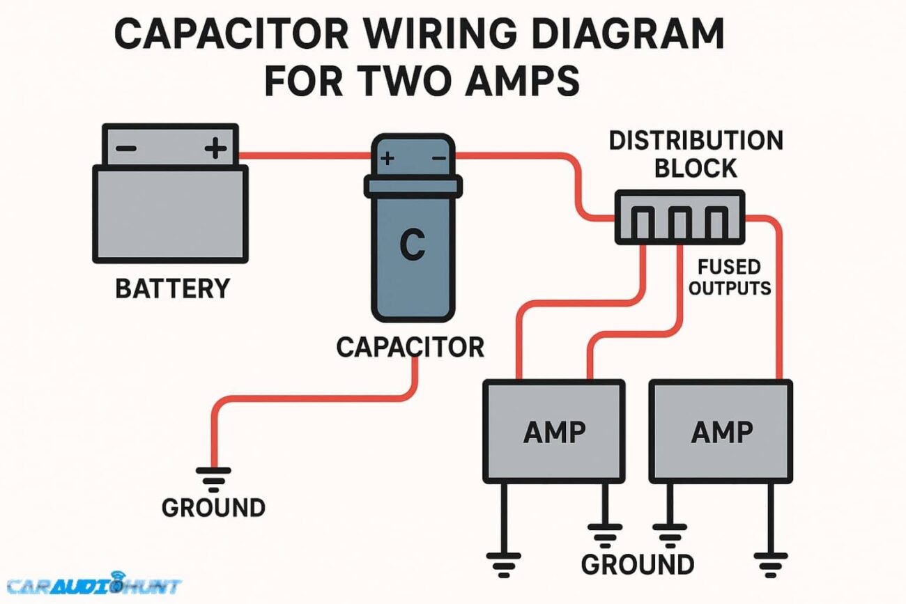
Car Audio Capacitor Wiring Diagram
Car Audio Capacitor Wiring Diagram
When looking at a car audio capacitor wiring diagram, you’ll typically see connections for the positive and negative terminals. The positive terminal connects to the battery, while the negative terminal should be grounded properly to avoid electrical issues.
It’s also important to connect the capacitor in parallel with your amplifier. This setup allows the capacitor to charge and discharge quickly, providing extra power during peak demands. Following the wiring diagram closely will help you achieve this setup effectively.
Additionally, ensure that you use appropriate gauge wires for your connections. Using wires that are too thin can lead to overheating and reduced performance. A good rule of thumb is to match the wire gauge with your amplifier’s requirements.
In conclusion, understanding a car audio capacitor wiring diagram is vital for any audio upgrade. Proper installation not only enhances sound quality but also protects your equipment from damage. Take your time to follow the diagram for the best results.