Understanding earphone jack wiring can be quite useful, especially if you’re into DIY electronics or need to troubleshoot audio issues. Knowing how to read a wiring diagram can save you time and money.
Many people overlook the importance of a good connection in their audio devices. A clear understanding of the earphone jack wiring diagram can help you maintain and repair your headphones effectively.

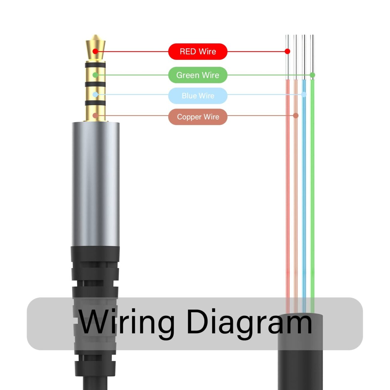
Earphone Jack Wiring Diagram
Earphone Jack Wiring Diagram
The earphone jack typically consists of three main sections: the tip, ring, and sleeve. Each part serves a specific function, allowing for stereo sound and microphone input. Understanding these components is crucial for any repairs.
In most standard earphone jacks, the tip carries the left audio channel, while the ring carries the right audio channel. The sleeve is usually connected to the ground. This configuration is essential for achieving balanced sound quality.
When working with an earphone jack wiring diagram, pay attention to color codes. Commonly, red indicates the right channel, white or green represents the left channel, and copper or bare wire signifies ground. These codes help simplify connections.
If you’re experiencing audio issues, refer to the wiring diagram before replacing your earphones. Often, a simple re-soldering of connections can restore functionality without needing new equipment.
Mastering the earphone jack wiring diagram can empower you to tackle audio problems confidently. With a little practice, you’ll find it easier to repair or customize your audio devices as needed.