Understanding how to wire an electric brake controller can significantly enhance your towing experience. Proper wiring ensures that your trailer brakes function effectively, providing safety and control on the road.
Many people find the process daunting, but with a clear electric brake controller wiring diagram, it becomes much simpler. This guide will help you navigate the essential steps for a successful installation.

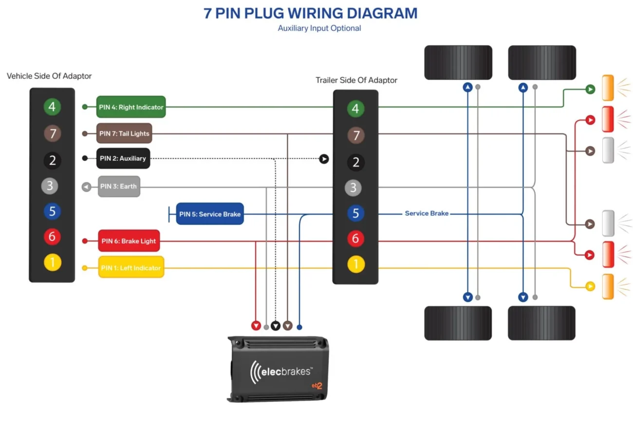
Electric Brake Controller Wiring Diagram
Electric Brake Controller Wiring Diagram
The electric brake controller wiring diagram serves as a roadmap for connecting your controller to the vehicle and trailer. It typically includes color-coded wires that correspond to specific functions, making installation straightforward.
Start by identifying the necessary components: the brake controller, wiring harness, and trailer brakes. Each part plays a crucial role in ensuring that your braking system operates smoothly and efficiently.
Next, follow the wiring diagram closely. Connect the power wire from the brake controller to your vehicle’s battery. Then, link the output wire to the trailer brakes. This connection is vital for activating the brakes when needed.
Finally, test the system before hitting the road. Ensure that all connections are secure and that the brakes respond correctly when activated. A well-installed electric brake controller can make all the difference during your travels.
With a clear understanding of the electric brake controller wiring diagram and proper installation, you can enjoy safer towing experiences. Take your time, follow each step carefully, and you’ll be ready for your next adventure.