Understanding electrical wiring can seem daunting, but with the right guidance, it becomes manageable. One essential aspect is the GFCI (Ground Fault Circuit Interrupter), which enhances safety in wet areas.
Learning how to connect GFCI outlets properly is crucial for any DIY enthusiast. A clear wiring diagram can simplify this process, ensuring you follow the correct steps for installation.

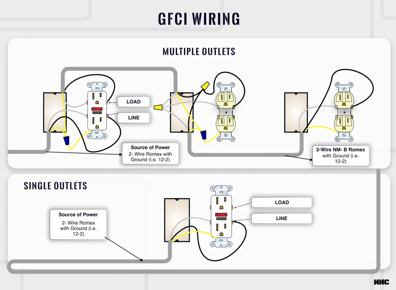
Gfci To Gfci Wiring Diagram
Gfci To Gfci Wiring Diagram
A GFCI to GFCI wiring diagram illustrates how to connect two GFCI outlets in a circuit. This setup is particularly useful in kitchens and bathrooms where moisture is prevalent.
When wiring GFCIs, always remember to turn off the power at the circuit breaker. This precaution helps prevent electrical shocks and ensures a safe working environment while you follow the diagram.
Each GFCI outlet has line and load terminals. The line connects to the power source, while the load can supply power to additional outlets downstream. Understanding this distinction is vital for proper installation.
After completing your wiring, test each GFCI outlet using the built-in test button. This step confirms that your installation is correct and that the outlets will function as intended, providing safety against electrical hazards.
With a clear understanding of the GFCI to GFCI wiring diagram, you can confidently tackle your electrical projects. Proper installation not only enhances safety but also ensures reliable performance in your home.