Understanding your vehicle’s components can significantly enhance your driving experience. One crucial part is the mass air flow sensor, which plays a vital role in engine performance and efficiency. Knowing how to read its wiring diagram can be beneficial.
The mass air flow sensor measures the amount of air entering the engine, helping to optimize fuel injection. A clear wiring diagram is essential for troubleshooting and repairs, ensuring your vehicle runs smoothly and efficiently.

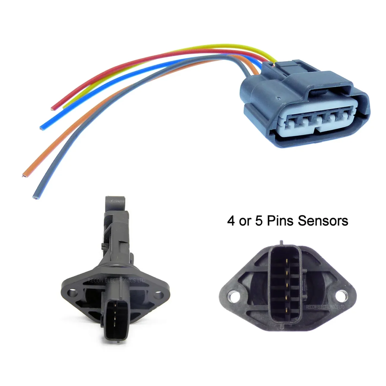
Mass Air Flow Sensor Wiring Diagram
Mass Air Flow Sensor Wiring Diagram
A mass air flow sensor wiring diagram typically includes color-coded wires that connect to the sensor and the engine control unit. Familiarizing yourself with these colors can simplify diagnostics and repairs. Each wire serves a specific function, making it easier to identify issues.
When examining the wiring diagram, pay attention to the voltage readings. These readings can indicate whether the sensor is functioning correctly or if there are underlying problems. Regular checks can prevent costly repairs down the line.
Additionally, understanding the layout of the wiring can help you avoid mistakes during installation or replacement. A clear diagram allows you to visualize connections, ensuring everything is in its proper place for optimal performance.
In conclusion, mastering the mass air flow sensor wiring diagram is a valuable skill for any car owner. It empowers you to maintain your vehicle effectively and enhances your overall driving experience. Stay informed and keep your car running smoothly!