Understanding relay wiring can seem daunting, but it’s quite straightforward once you break it down. A relay is a crucial component in many electrical systems, allowing you to control high-power devices with low-power signals.
One common type is the 4-pin relay, often used in automotive applications. Knowing how to read a Relay 4 Pin Wiring Diagram can help you troubleshoot and set up your circuits effectively.

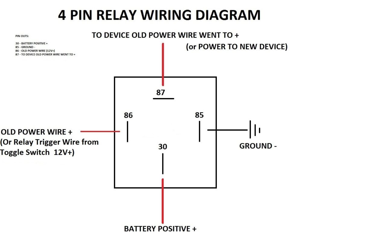
Relay 4 Pin Wiring Diagram
Relay 4 Pin Wiring Diagram
The Relay 4 Pin Wiring Diagram typically includes four terminals: two for the coil and two for the switch. The coil pins activate the relay, while the switch pins control the connected device.
When wiring, connect one coil pin to your power source and the other to ground. This setup allows current to flow through the coil, energizing the relay and closing the switch circuit.
For the switch side, connect one pin to your load and the other to your power source. This configuration enables the relay to control high-power devices safely without direct interaction with low-power signals.
Always double-check your connections against the Relay 4 Pin Wiring Diagram before powering up. Incorrect wiring can lead to malfunction or damage to your components.
Mastering the Relay 4 Pin Wiring Diagram opens up a world of possibilities for DIY projects and repairs. With practice, you’ll gain confidence in handling various electrical tasks efficiently.