Understanding the wiring of a Triton gas solenoid valve can seem daunting, but it’s essential for ensuring proper functionality. With the right guidance, you can easily navigate through the wiring process and enhance your system’s performance.
Having a clear wiring diagram at hand simplifies the installation and troubleshooting of your gas solenoid valve. This article will provide insights into the Triton gas solenoid valve wiring diagram, making it easier for you to follow along.

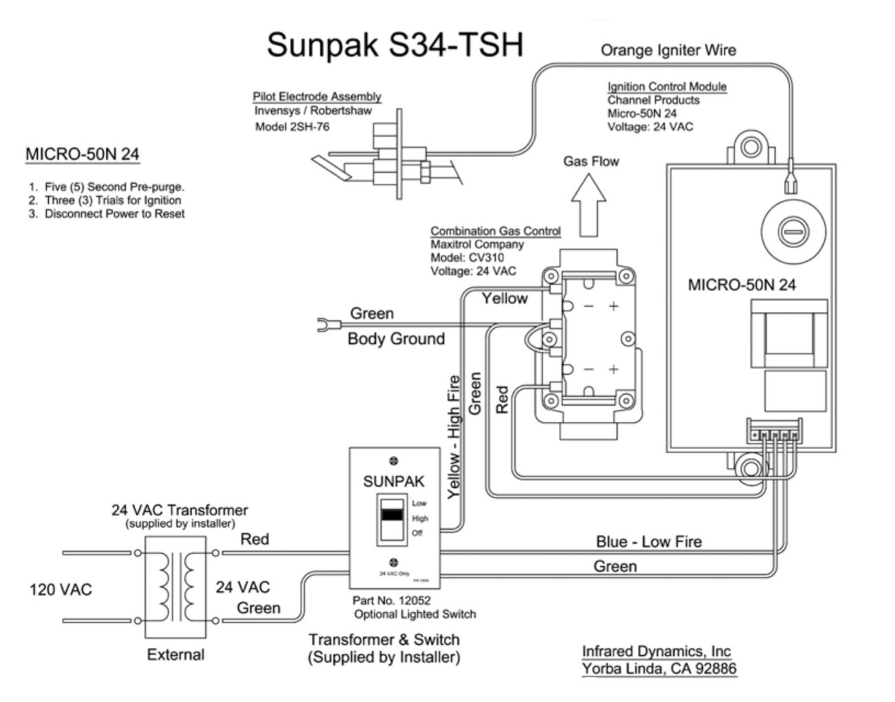
Triton Gas Solenoid Valve Wiring Diagram
Triton Gas Solenoid Valve Wiring Diagram
The Triton gas solenoid valve typically features two main terminals: one for power and another for grounding. Understanding these connections is crucial for safe and effective operation of your gas system.
When wiring the solenoid valve, always ensure that the power supply is turned off. This precaution prevents any electrical hazards while you work on the connections. Following the wiring diagram closely will help avoid mistakes.
It’s also important to use appropriate wire gauges to handle the current load. Using wires that are too thin can lead to overheating and potential failure of the solenoid valve. Always refer to manufacturer specifications for guidance.
After completing the wiring, double-check all connections before powering up the system. A thorough inspection can save you from future headaches and ensure that everything operates smoothly.
With a solid understanding of the Triton gas solenoid valve wiring diagram, you can confidently tackle your installation or repair project. Proper wiring not only enhances safety but also improves overall system efficiency.