Understanding the Trrs connector wiring diagram can be quite beneficial for anyone working with audio equipment. This knowledge helps in troubleshooting and ensuring optimal performance of your devices, making it easier to connect various audio sources.
Whether you’re a musician, sound engineer, or just a tech enthusiast, grasping the basics of Trrs connectors is essential. These connectors are commonly used in headphones and microphones, providing a seamless audio experience.

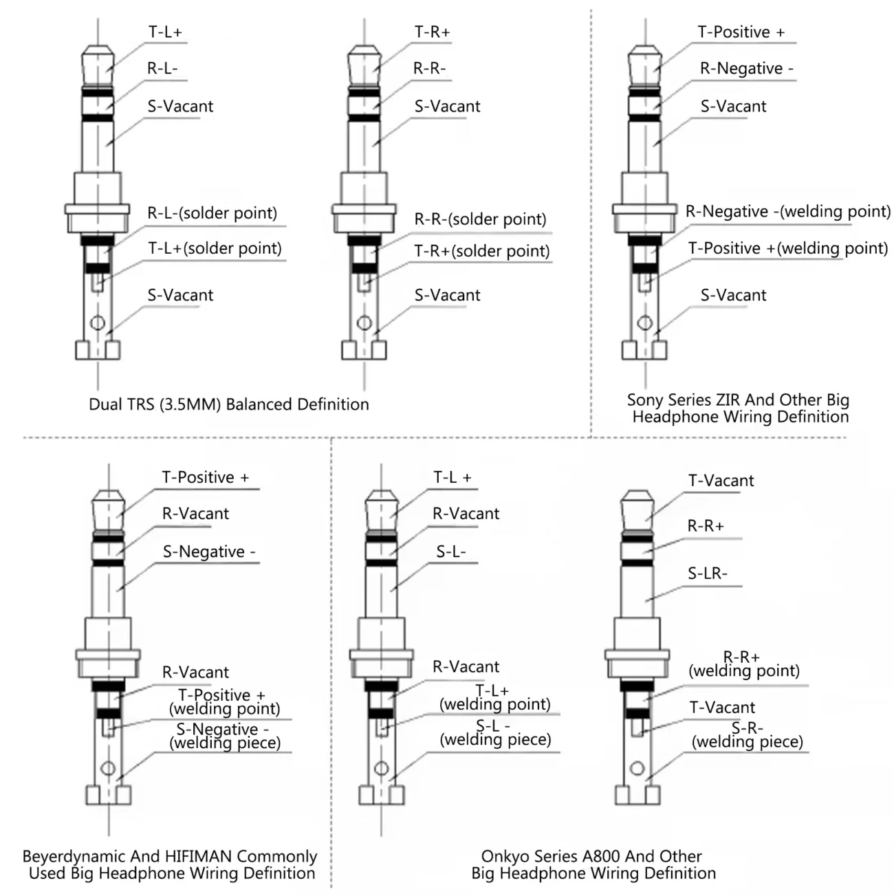
Trrs Connector Wiring Diagram
Trrs Connector Wiring Diagram
The Trrs connector features four conductors: Tip, Ring 1, Ring 2, and Sleeve. Each part plays a crucial role in transmitting audio signals and microphone input. Understanding these components is key to effective wiring.
When looking at the Trrs wiring diagram, you’ll notice that the Tip typically carries the left audio channel. Meanwhile, Ring 1 is used for the right audio channel, ensuring a stereo sound experience for users.
Ring 2 is designated for the microphone input, allowing for clear voice transmission during calls or recordings. The Sleeve serves as the ground connection, completing the circuit and ensuring stable performance.
By familiarizing yourself with the Trrs connector wiring diagram, you can easily troubleshoot issues or create custom cables tailored to your needs. This knowledge empowers you to enhance your audio setup effectively.
In conclusion, mastering the Trrs connector wiring diagram opens up new possibilities for audio enthusiasts. With this understanding, you can confidently tackle any audio project and enjoy high-quality sound experiences.