Understanding the intricacies of well pump control box wiring can seem daunting at first. However, with the right guidance and resources, anyone can tackle this task with confidence and ease. A clear wiring diagram is essential for successful installation.
Proper wiring ensures that your well pump operates efficiently and safely. Familiarizing yourself with the components involved will help you troubleshoot any issues that may arise. Let’s dive into the details of a well pump control box wiring diagram.

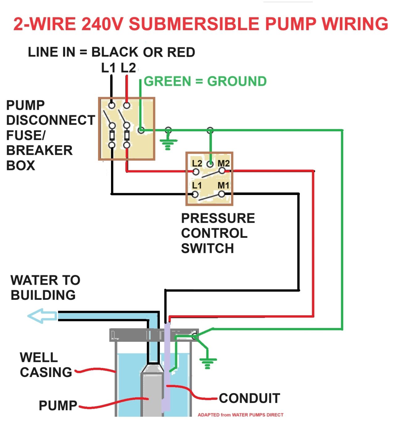
Well Pump Control Box Wiring Diagram
Well Pump Control Box Wiring Diagram
A well pump control box typically includes various components such as relays, capacitors, and fuses. Each part plays a crucial role in regulating the pump’s operation. Understanding these components is vital for effective wiring.
When examining a well pump control box wiring diagram, pay attention to the color-coded wires. These colors indicate specific functions, making it easier to connect everything correctly. Following the diagram closely will prevent potential mishaps during installation.
Additionally, safety should always be a priority. Ensure that the power is turned off before starting any wiring work. This precaution helps avoid electrical shocks and ensures a smooth installation process.
In conclusion, mastering the well pump control box wiring diagram can empower you to manage your well system effectively. With patience and attention to detail, you’ll ensure your well pump runs smoothly for years to come.