Understanding how to use a 5 pin relay can simplify many electrical projects. Whether you’re working on automotive applications or home automation, having a clear wiring diagram is essential for success.
A wiring diagram helps visualize connections and ensures everything is set up correctly. This guide will provide insights into the wiring diagram for a 5 pin relay, making your projects easier and more efficient.

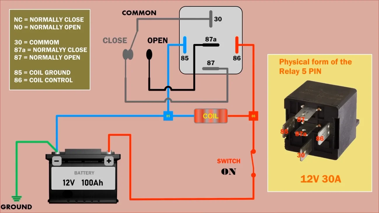
Wiring Diagram For 5 Pin Relay
Wiring Diagram For 5 Pin Relay
A 5 pin relay typically includes terminals for the coil and contacts. The coil pins activate the relay, while the contact pins manage the load. Knowing which pin does what is crucial for proper installation.
In most cases, the relay has two coil terminals, which connect to a power source. When voltage is applied, the relay activates, allowing current to flow through the contact terminals. This action can control various devices effectively.
It’s important to identify the normally open (NO) and normally closed (NC) contacts in your wiring diagram. The NO contact closes when the relay is activated, while the NC contact opens. This distinction is vital for correct functionality.
When wiring your 5 pin relay, always double-check connections to avoid short circuits. Using color-coded wires can help keep everything organized and prevent confusion during installation.
With a clear understanding of the wiring diagram for a 5 pin relay, you can tackle your electrical projects with confidence. Proper setup leads to reliable performance and enhances your overall experience.