Understanding electrical systems can be daunting, especially when it comes to components like pressure switches. Having a clear wiring diagram can simplify the installation and troubleshooting process significantly. This guide will help you navigate through it.
Pressure switches are essential in various applications, from HVAC systems to industrial machinery. Knowing how to read and interpret a wiring diagram for these switches is crucial for effective maintenance and repair. Let’s dive into the details.

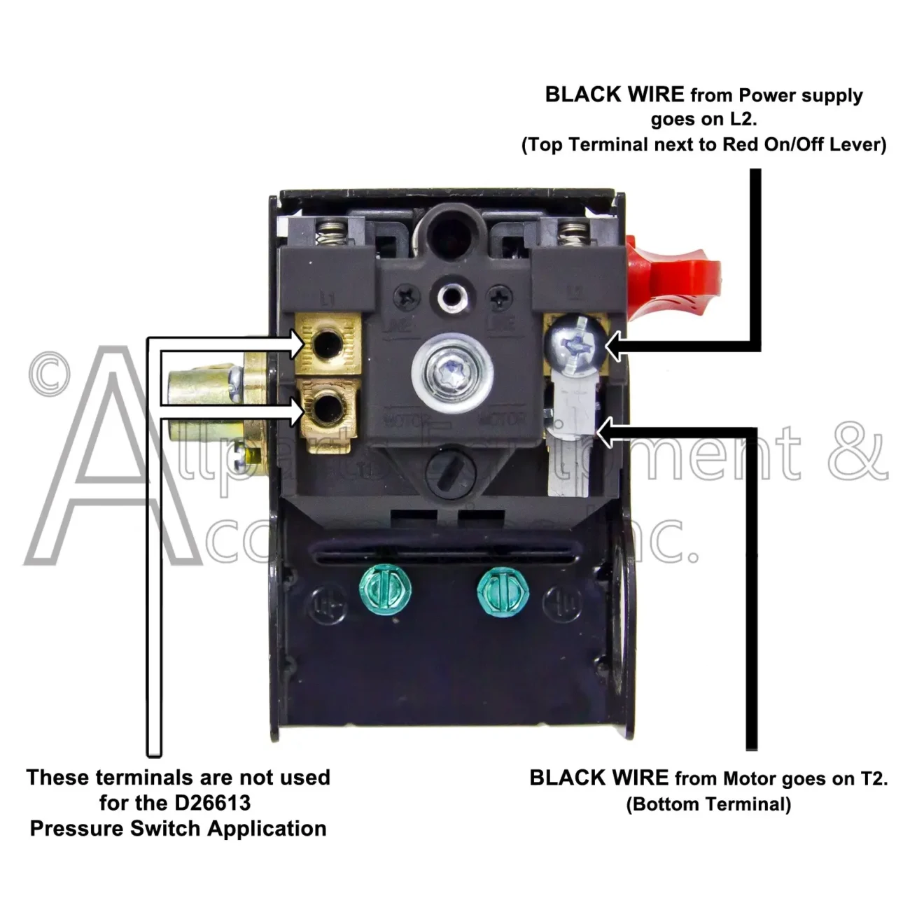
Wiring Diagram For Pressure Switch
Wiring Diagram For Pressure Switch
A wiring diagram for a pressure switch typically includes symbols representing the switch, power source, and load. Familiarizing yourself with these symbols can make understanding the connections much easier. Each component plays a vital role in the overall system.
When looking at a wiring diagram, pay attention to the color codes of the wires. These codes indicate which wire connects to the power source and which connects to the load. Correctly identifying these wires ensures safe and efficient operation.
It’s also important to note the pressure settings indicated on the diagram. These settings determine when the switch activates or deactivates, impacting your system’s performance. Always refer to manufacturer specifications for accurate information.
In summary, a wiring diagram for a pressure switch is an invaluable tool for anyone working with electrical systems. By understanding its components and connections, you can ensure your systems run smoothly and efficiently.