Understanding the wiring diagram for turn signals is essential for any vehicle owner. It helps in troubleshooting issues and ensures that your turn signals function correctly, enhancing safety on the road.
Whether you’re a DIY enthusiast or just want to know more about your vehicle’s electrical system, having a clear wiring diagram can make all the difference. This guide will simplify the process for you.

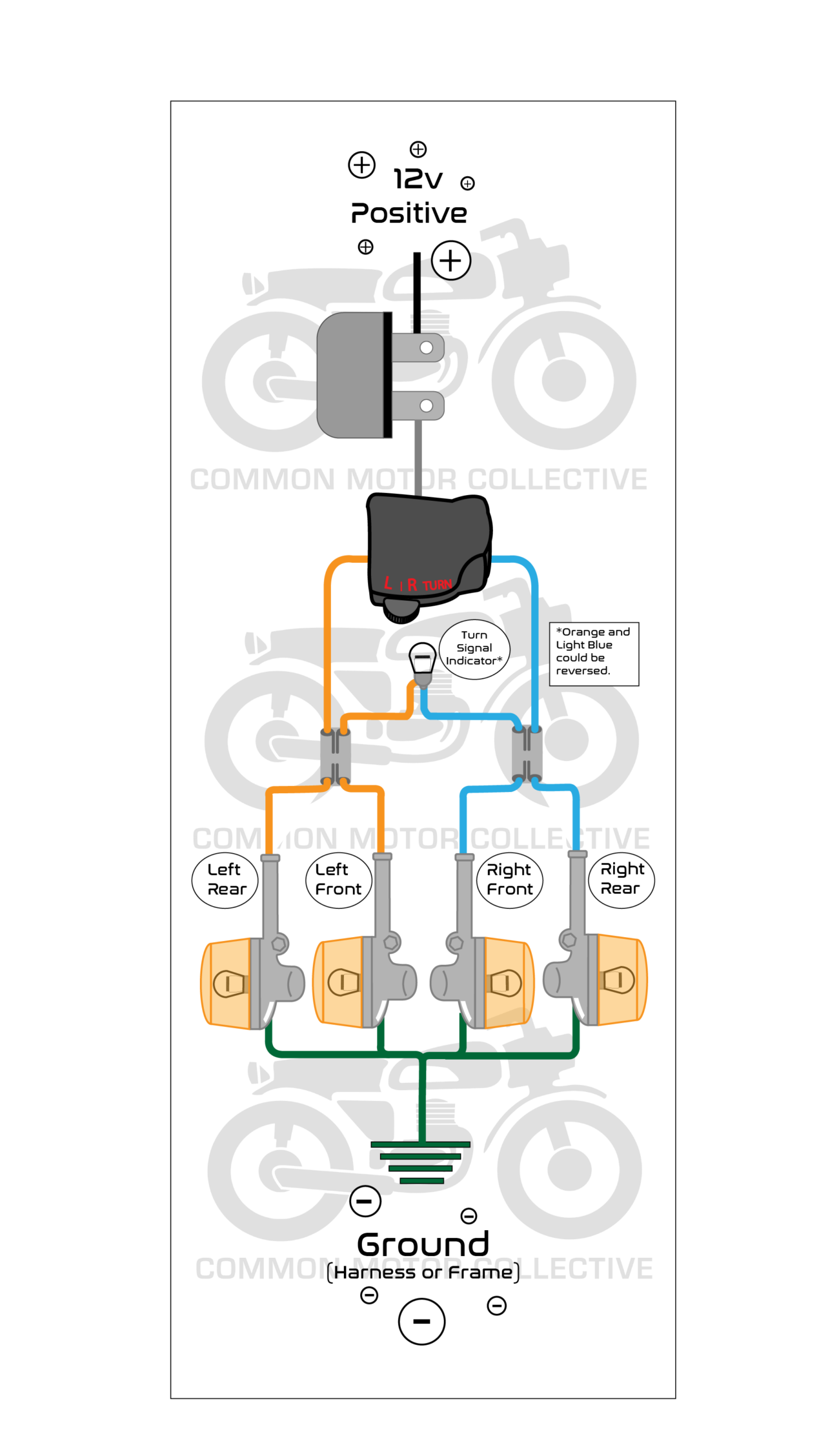
Wiring Diagram For Turn Signals
Wiring Diagram For Turn Signals
A wiring diagram for turn signals typically includes color codes and connection points. Knowing these details allows you to identify which wires control the left and right signals effectively.
Most vehicles have a standard setup, but variations exist. Familiarizing yourself with your specific model’s wiring can prevent confusion and ensure accurate repairs or installations.
When working with turn signals, always prioritize safety. Disconnect the battery before starting any electrical work to avoid shocks or short circuits. This simple step can save you from potential hazards.
Additionally, if you’re unsure about any connections, consulting a professional is wise. They can provide guidance and ensure everything is wired correctly, keeping your vehicle safe on the road.
In conclusion, understanding the wiring diagram for turn signals empowers you to maintain your vehicle effectively. With the right knowledge and precautions, you can tackle any electrical issue confidently.